OpenEnergyMonitor - emonTx - Build Guide
Building an emonTx
Guide created and maintained by: Ian Chilton - please direct any suggestions or corrections to: ian [at] ichilton [dot] co [dot] uk.
If you get stuck, there is a forum and a lot of other information over at OpenEnergyMonitor.
Introduction
Here's how to build up an emonTx as a step by step guide.
OpenEnergyMonitor is project to develop and build open-source energy monitoring, control and analysis tools. The main focus at the moment is developing an end-to-end open-source energy monitoring system that is Arduino IDE compatible. More information can be found at: http://openenergymonitor.org
emonTx is a low power wireless energy monitoring node. It's designed to sense data from multiple CT current sensors, optically from a pulse-output utility meter and from multiple one-wire temperature sensors. It can be powered by 2 x AA batteries or 5V USB.

The pcb is built in an orderly sequence starting with the resistors and small components that are low on the board and then working up to the bulkier parts like connectors. After soldering each component, you need to cut off the excess lead from the bottom using some cutters.
It is very easy to cause shorts which will make the board or specific parts of it not work. What i'd advise is that you take your time during the build, be precise, use minimal solder and carefully check each joint after soldering it. If you suspect any short, check it with a multimeter and fix any shorts there and then, before continuing.
Even if you have been soldering for years, i'd highly recommend these videos to get the right tools and improve your technique:
- EEVBlog Soldering Tutorial - Part 1: Tools
- EEVBlog Soldering Tutorial - Part 2: Soldering
- EEVBlog Soldering Tutorial - Part 3: Surface Mount
It's recommended you read through the whole of this guide and familiarise yourself with the steps before you start the actual build.
Step 1 - Identify Components and Kit Contents
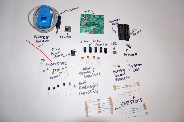
Layout and identify the components from the kit.
 |
| From OpenEnergyMonitor - emonTx Build |
Here are all the components required to build your emonTx:
- The emonTx PCB
- 3x 18 ohm 1% Resistors (brown, grey, black, gold, brown on blue)
- 2x 10k 1% Resistors (brown, black, black, red, brown on blue)
- 1x 100k 1% Resistor (brown, black, black, orange, brown on blue)
- 8x 470k Resistors (yellow, violet, yellow, gold)
- 1x 4k7 Resistor (yellow, violet, red, gold)
- 1x 100 ohm Resistor (brown, black, brown, gold)
- 4x 100nF (0.1uF) Ceramic Capacitors
- 5x 10uF Electrolytic Capacitors
- 2x 22pF Ceramic Capacitors
- 1x Atmel ATMega328 - the main microcontroller
- 1x 28-Pin DIL Socket
- 1x RFM12B Radio Module - available in 433Mhz or 868Mhz versions
- 1x 165mm (433Mhz) or 82mm (868Mhz) Wire for RFM12B Antenna
- 1x 16Mhz Crystal - for the ATMega328.
- 1x USB Mini B Socket
- 1x Microchip MCP1702 3.3v Voltage Regulator
- 1x 3mm Green LED
- 1x 2.1mm Power Socket
- 5x 3.5mm Jack Sockets
- 100A CT Clamp
 |
| From OpenEnergyMonitor - emonTx Build |
Note that the photo shows two different types of the 22pF capacitors - brown ceramic disc (labelled 22 and with black tops) and small blue ones - only one of these pairs are required/included and they are equivelent.
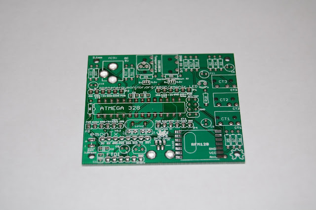
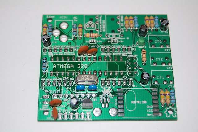
Ok, we're ready to start. Here is the PCB ready:
 |
| From OpenEnergyMonitor - emonTx Build |
 |
| From OpenEnergyMonitor - emonTx Build |
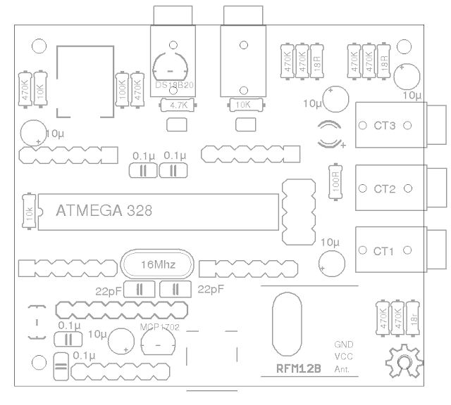
This is where everything should go:
 |
| From OpenEnergyMonitor - emonTx Build |
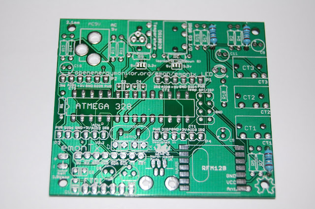
Please note that despite the diagram above and the photo below, we do not fit the 10k resistor under the pulse counting socket at the top of the board as this can cause problems.

Please note the above photo is from an older version of the board and therefore is slightly different (eg: some of the resistor values have changed) - it's just here to show the various parts of the board.
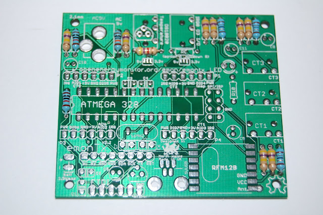
Step 2 - 18 ohm Resistors
Start with the resistors. Bend each leg of the resistor over 90 degrees, right next to the body. It's recommended that you align them all in the same direction.
First we add the 3x 18 ohm resistors - they are blue and their colour code is: Brown, Grey, Black, Gold, Brown.
 |
| From OpenEnergyMonitor - emonTx Build |
Step 3 - 10k Resistors
Add the 2x 10k resistors - they are blue and their colour code is: Brown, Black, Black, Red, Brown.
 |
| From OpenEnergyMonitor - emonTx Build |
Note that the diagram above shows a 3rd 10k resistor - under the pulse counting input (R8). This is an optional pull down resistor for the pulse counting interrupt input / general digital I/O. More often than not it's not needed so is not included in the kit as if fitted, it will do more harm than good e.g if 10K resistor is soldered into R8 an optical sensor plugged into this port to detect the LED pulses from pulse output meters won't work.
R8 is only actually useful when connecting directly (via wire) to the pulse output from a utility meter, we're not recommending this method since it's not galvanically isolated and to connect the wires you have to work very close to high voltage, not ideal. Optical pulse detection is much safer.
Step 4 - 100k Resistor
Add the 100k resistor - it's blue and it's colour code is: Brown, Black, Black, Orange, Brown.
 |
| From OpenEnergyMonitor - emonTx Build |
Step 5 - 470k Resistors
Add the 8x 470k resistors - their colour code is: Yellow, Violet, Yellow, Gold.
 |
| From OpenEnergyMonitor - emonTx Build |
Step 6 - 4k7 Resistor
Add the 4k7 resistor - it's colour code is: Yellow, Violet, Red, Gold.
 |
| From OpenEnergyMonitor - emonTx Build |
Step 7 - 100 ohm Resistor
Add the 100 ohm resistor - it's colour code is: Brown, Black, Brown, Gold.
 |
| From OpenEnergyMonitor - emonTx Build |
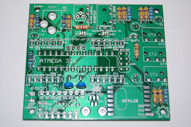
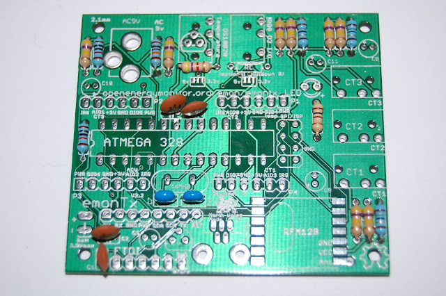
Step 8 - 22pF Ceramic Capacitors
Add the 2x 22pF ceramic capacitors - they are either blue (as per the photo) or small brown discs with black tips.
 |
| From OpenEnergyMonitor - emonTx Build |
Step 9 - 100nF Ceramic Capacitors
Add the 4x 100nF ceramic capacitors - they are labelled 104.
 |
| From OpenEnergyMonitor - emonTx Build |
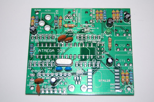
Step 10 - 10uF Electrolytic Capacitors
Add the 5x 10uF electrolytic capacitors. These must go the correct way round. The PCB is marked with a + symbol to indicate positive lead. The capacitors are marked with a white strip and a short leg to indicate the negative lead and a longer leg to indicate the positive lead.
 |
| From OpenEnergyMonitor - emonTx Build |
Step 11 - 16Mhz Crystal
Add the 16Mhz crystal - it can go either way round.
 |
| From OpenEnergyMonitor - emonTx Build |
Step 12 - Green LED
Add the green LED. The PCB is marked with a + symbol to indicate positive. The LED has a short leg (and flat edge) to indicate the negative leg and a longer leg to indicate the positive leg.
 |
| From OpenEnergyMonitor - emonTx Build |
Step 13 - MCP1702 3.3v Voltage Regulator
Add the MCP1702 3.3v Voltage Regulator - the flat edge goes towards the bottom of the board as per the markings.
 |
| From OpenEnergyMonitor - emonTx Build |
Step 14 - Mini USB Socket
Add the mini USB socket.
 |
| From OpenEnergyMonitor - emonTx Build |
Step 15 - 3.5mm Sockets
Add the 5x 3.5mm sockets.
 |
| From OpenEnergyMonitor - emonTx Build |
Step 16 - 2.1mm Power Socket
I added the 2.1mm power socket next, but it would actually be better to add this after the DIL socket (next step) as the DIL socket will fit flush on the desk while you solder it.
 |
| From OpenEnergyMonitor - emonTx Build |
Step 17 - DIL Socket
Add the DIL socket. If you are observant, you will notice that I put it the wrong way around on the photos! - the notch on the socket should go to the left of the board, as per the markings on the PCB.
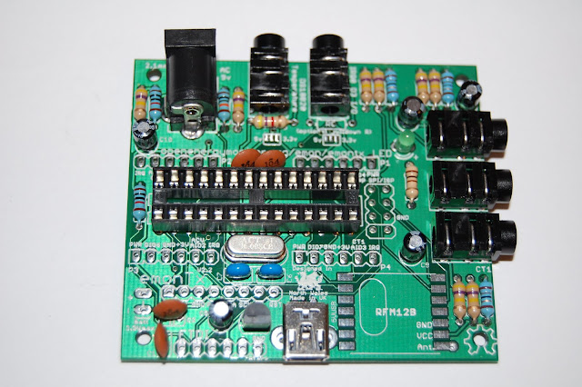 |
| From OpenEnergyMonitor - emonTx Build |
Step 18 - Programming Header
Add the 6-pin programing header at the bottom of the board.
 |
| From OpenEnergyMonitor - emonTx Build |
Step 19 - Voltage Check
We now need to check the voltage is correct before we add any of the expensive components. Power the board with either an FTDI programming cable or a mini USB and measure the voltage between the GND and VCC pads on the RFM12B socket. You should get 3.3v. If you get more than this, you should work out what has gone wrong before you continue.
 |
| From OpenEnergyMonitor - emonTx Build |
Step 20 - RFM12B
Add the RFM12B module. You can see the shapes of the crystal on the PCB. Position the module in place over the pads and gently apply heat and solder the opposite corners to hold it in place so you can solder the remaining pads.
 |
| From OpenEnergyMonitor - emonTx Build |
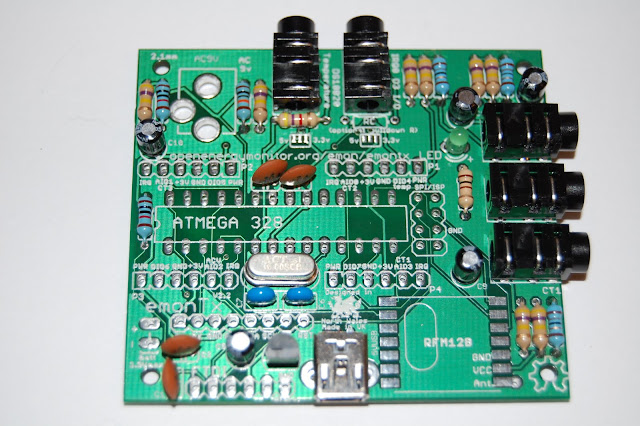
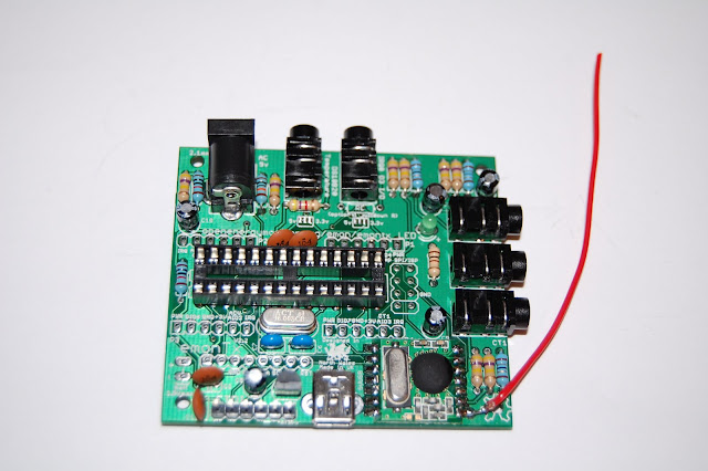
Step 21 - Antenna
Add the antenna by soldering the end to the bottom right pad on the RFM12B module.
 |
| From OpenEnergyMonitor - emonTx Build |
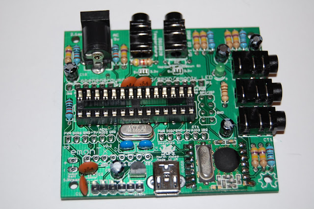
Completed Board
We can now add the ATMega328 chip. You will need to bend the pins in slightly by resting the chip sidewards on the desk and rolling it fowards to bend the pins in. Do the same with the other side.
 |
| From OpenEnergyMonitor - emonTx Build |
 |
| From OpenEnergyMonitor - emonTx Build |
 |
| From OpenEnergyMonitor - emonTx Build |
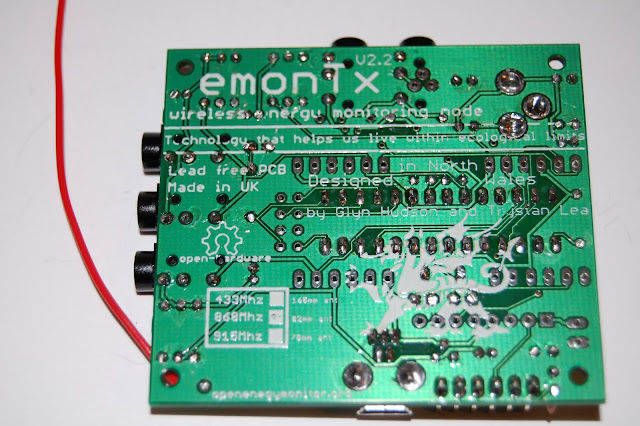
Voltage Selection Notes
On this latest version of the emonTx PCB, two solder jumpers have been added by the IRQ I/O and temperature (DS18B20) ports. They allow the user to decide what voltage to use on these ports. The emonTx runs at 3.3V. More explanation can be found in this blog post. Connection is made by joining the middle pad the either of the outer pads with solder.
If you look careful the solder jumper above the temperature port is connected to 5V (small PCB trace). This was an error, but actually work out well. The temperature sensors always use 5v (which is good) and when the emonTx is powered by 2 x AA's the the 5V rail becomes 3.3V anyway. Therefore, you can ignore this solder jumper, it will disappear in the next generation of emonTx PCB's.
Firmware Upload
ATmega will come with Arduino Optiboot 4.4 bootloader (select Uno in IDE) but with no sketch uploaded. The correct sketch must be uploaded using Arduno IDE.
Coming Soon - detail of sketch and how to upload.
Connections
Coming Soon
Testing
Coming Soon